
Likewise, it is very difficult (and potentially lethal) to attempt to capture all the voltages and currents that exist in real fluorescent lamp circuits. the simulator cannot represent a negative impedance load with appropriate strike voltages and other characteristics that a fluorescent tube presents. Where necessary, the simulated waveforms are corrected to match those measured. Note that the waveforms shown here are a combination of simulations and actual measurements. This article shows some of the ways these goals are achieved, starting from the basic inductive ballast that has been the mainstay of fluorescent lamp production for many years. When first started, it is necessary to provide a significantly higher voltage than normal to cause the internal arc to strike, and once started, the current must be limited to a safe value for the tube.

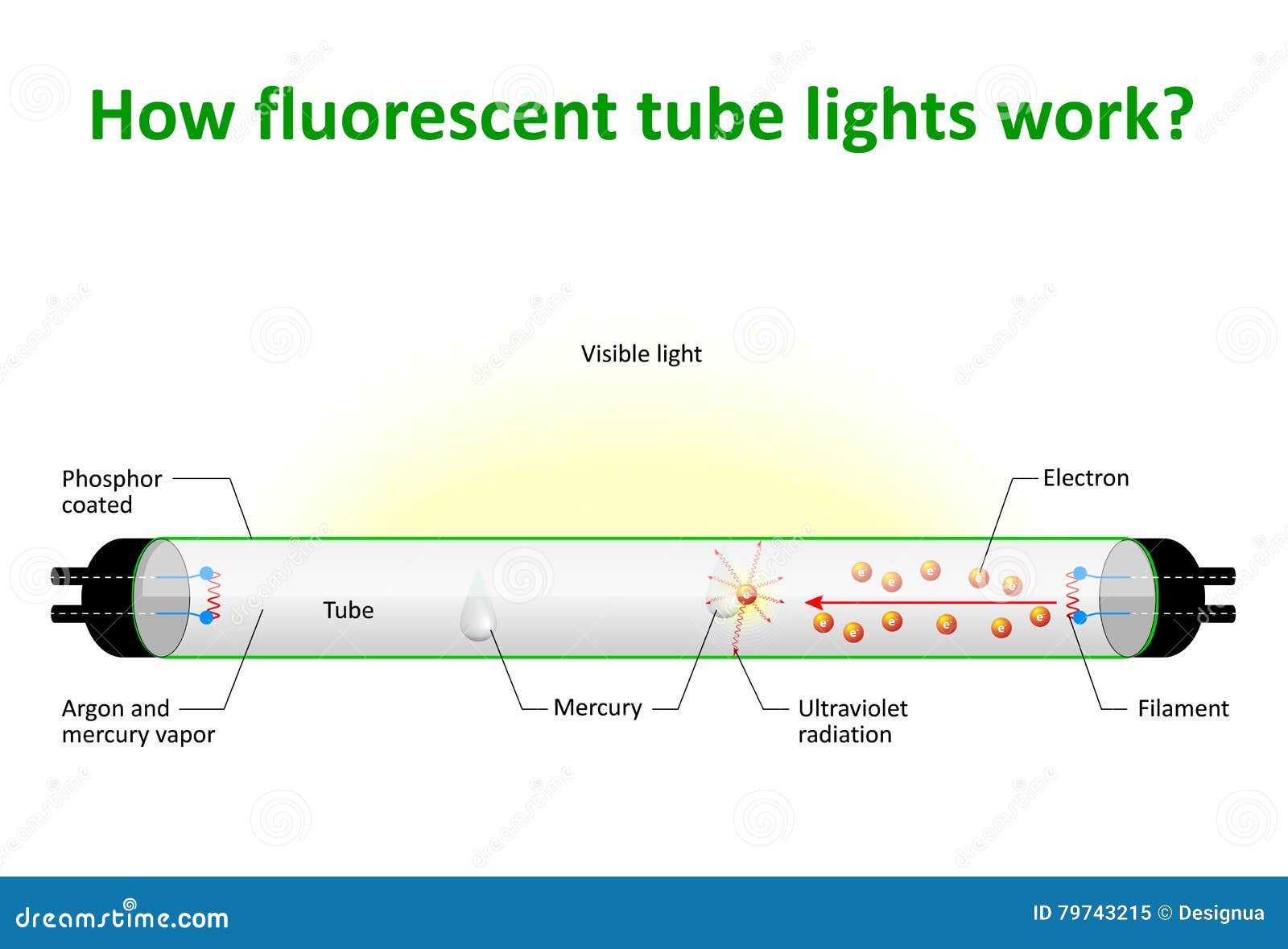
The way a fluorescent lamp works is very different from a simple incandescent lamp, and modern fluorescents (especially the compact fluorescent lamp, or CFL) make use of electronic ballasts to regulate the voltage across the lamp, and the current through it.

It's not covered here, because this is about how they work, rather than a discussion of the way fittings are wired. There are alternative ballast schemes used (such as the 'lead/ lag' arrangement) and this is shown in the previous article. The article Traditional Fluorescent Tube Lamps & Their Alternatives looks at the operation of fluorescent lamps in fairly simple terms, but here we will examine the lamps, their ballasts (both 'traditional' magnetic and electronic types) and delve a little deeper into their inner workings.


 0 kommentar(er)
